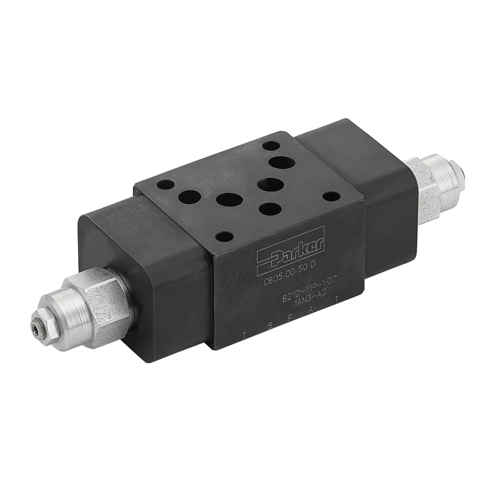
1.What is a balancing valve?
Compared with other hydraulic valves, the balancing valve is called a special hydraulic valve because of its different functions and places of use.
In many applications, the direction of the load force is the same as the direction of movement. At this time, the speed can be controlled by a throttle valve, a reversing valve, a two-way flow valve, etc. The most common one is a balancing valve. Because the balancing valve is a combination valve with multiple functions.
The oil in the hydraulic system has a large pressure difference or flow difference in various parts of the pipeline. To reduce this difference, a balancing valve will be configured in the corresponding pipeline to adjust the pressure on both sides to keep it relatively balanced, or to achieve flow balance through diversion.
2.How does the balancing valve work?
The working principle of the counterbalance valve is that the fluid of the hydraulic system can flow freely into the actuator through the check valve, and the reverse flow is blocked by the relief valve until the preset pressure and load capacity based on the system pressure setting is reached.
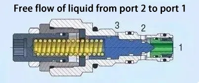
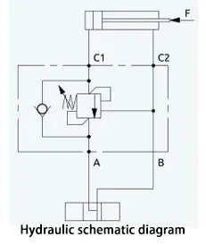
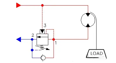
① The balancing valve opens in the forward direction: As shown in the figure below, when the oil pressure at valve port 2 is greater than that at valve port 1, the valve core in the green part moves toward valve port 1 under the drive of the hydraulic pressure, the one-way valve opens, and the oil flows from valve port 2 to valve port 1.
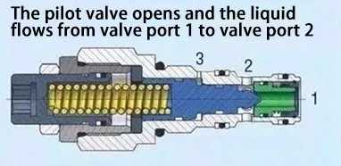
② Reverse opening of the balancing valve: When the pressure of the pilot port 3 reaches the set value, the blue valve core moves to the left, the valve port is opened, and the oil can flow from valve port 1 to valve port 2. When the pressure of the pilot valve is not enough to open the blue valve core, the valve port is closed, and the flow from valve port 1 to valve port 2 is cut off.
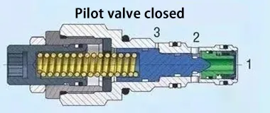
③ When the pressure at pilot port 3 disappears, the valve is lower than the set value, closes, and the load remains in place.
3.Function and application of balancing valve
The balancing valve is also called load holding valve, which is used to safely reduce and control the load at high speed. Load holding, load control and safety are the three important functions of the balancing valve.
①. Load holding: The balance valve allows the actuator to lift or lower the weight at a certain speed and keep it in a certain position.

②. Load control: When the hydraulic cylinder in the lifting equipment is lowered with load, if there is no balance valve, the mechanism will fall at an overspeed under the action of the load. The balance valve can effectively control the smooth movement of the actuator under the action of the load to prevent the loss of control due to load changes.
③. Safe load: When the pipeline in the hydraulic oil circuit bursts or leaks seriously, the balance valve installed on the actuator can prevent the loss of control of the moving load. When the load holding device fails, it will not only cause property damage, but may also endanger life. Balance valves are mainly used in load holding equipment, such as cranes, amusement park rides, boom trucks, etc. Balance valves are common safety components in this equipment to improve safety.

4.Key parameter settings of balancing valve
①Balance valve pressure: The set pressure of the pilot port of the balance valve will determine the direction in which the load can move. The pressure setting value of the balance valve generally refers to the set value of its pilot port.
Set the pressure of the balance valve according to the weight of the load supported by the hydraulic system. When other factors are constant, the heavier the load, the greater the working pressure of the hydraulic system, and the greater the set pressure of the balance valve. According to experience, it is recommended that its setting value be 1.3 times the maximum working pressure. For example, when the working pressure of the hydraulic system is 21MPa, the set pressure of the balance valve is 21x 1.3=27.3MPa.
The balance valve pressure is generally set by the supplier at the factory and does not need to be adjusted later. After adjustment, the load may not be supported, and hydraulic cylinder creeping may occur. The balance valve was adjusted during the hydraulic cylinder test, and it was not restored to the factory value, causing the hydraulic cylinder to creep. After the balance valve pressure is reset according to regulations, the hydraulic cylinder creep disappears.
② Opening pressure
For conventional balancing valves, ignoring the influence of return oil pressure, the opening pressure = (set pressure – load pressure) / (pilot ratio + cylinder area ratio), which is generally 1/3 of the working pressure.
③ Pilot ratio: It is the ratio of the pressure to open the balancing valve when there is no pilot oil to the pressure to open the valve with the pilot oil alone. Generally, it is 3:1, which is suitable for conditions with large load changes. It can be set to 8:1 when the load is required to remain constant.
The choice of pressure ratio is different in different working occasions and environments. When the load is simple and the external interference is small, a large hydraulic control ratio is generally used, which can reduce the pilot pressure value and save energy. In situations where the load interference is large and vibration is easy, a smaller pressure ratio is generally selected to ensure that the fluctuation of the pilot pressure will not cause frequent vibration of the balancing valve core.
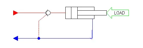
5. Difference from hydraulically controlled check valve
Both the hydraulically controlled check valve and the balancing valve have a load holding function and have the following characteristics:
①Prevent the load from falling if a hose or pipeline fails.
② Prevent load drift caused by leakage from the directional control valve slide valve;
③ Leak-free load holding.
The difference between the two is:
The hydraulically controlled check valve is a switch valve, not a continuous valve, and has no throttling function. The balance valve is a continuous valve and has a hydraulically controlled throttling function when descending.
Different applications: The hydraulically controlled check valve is suitable for use in situations with light loads. Typical applications include positioning the cylinder when the reversing valve is in the middle position, keeping the fixture in place, or keeping the tool in place.
The balancing valve is suitable for occasions with relatively large load changes and is suitable for smooth control and load override control.
If a hydraulically controlled one-way valve is used in situations with heavy loads, problems such as failure to lock and loud noise may occur. At this time, a suitable balancing valve should be selected according to the load conditions to ensure stable operation of the system while also solving the noise problem.
For simple load holding applications, a pilot operated check valve is suitable and more economical. For more demanding load holding and motion control requirements, a counterbalance valve is the solution and is worth the extra expense.